Welcome to Robotics Info Technology
By Ashraf Abdulai
Portfolio Entry -1 (Basic circuits and Programming)
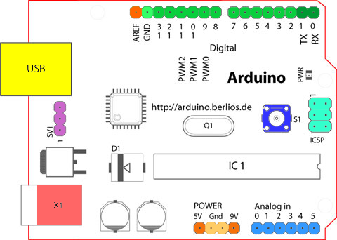
Arduino Layout
Arduino Uno is a microcontroller board developed by Arduino.cc which is an open-source electronics platform mainly based on AVR microcontroller Atmega328. The Arduino Uno is programmed using the Arduino IDE. Arduino consists of many input /outputs pins that can be attached to different circuits and breadboards. There are Digital pins which are used for general input and output, power pins to supply power to any external component, USB port to power up an Arduino a from a computer or another device, power jack to provide direct power supply(DC) to the Arduino. It also powers light to indicate that the Arduino is on. Digital pins range from pin 0 to pin 13. Analog pins range from 0 to 5 The reset button is used to restart the Arduino.
Circuit design, diagrams and symbols
An electronic circuit is a circuit that has electronic components like resistors, batteries, LEDs, capacitors connected together with wires through which current can flow.
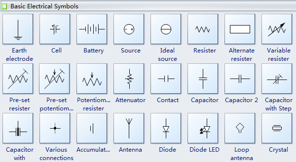
A circuit design is a way a circuit is planned and created to serve a purpose and a circuit diagram is the graphical representation of a circuit design. Circuit diagrams use the circuit symbols to represent each component in the circuit. Some examples of the symbols are shown below.
Uses of resistor
Firstly, what is a resistor? In my own words, a resistor restricts the flow of current in a circuit. Resistors are used to adjust or change the signal in a circuit. Resistors regulate the current flowing through a circuit to make sure that the components in the circuit do not receive too much power. They can be used in radios, tv’s, electric heaters and ovens and many more.
Use of Multimeters
A multimeter is an electronic device used to measure the current, voltage and resistance of components in a circuit. It has a display panel to show what is being measured and its value. A switch to choose the measurement and turn it off. Probes (black – and red +) to touch the component or object being measured. Multimeters are mostly used by engineers and technicians.
Inputs and Outputs devices
An input device is devices that give raw data to the computer. Output devices bring out information to the end-user. There are many input and output devices some are;
LED(Light Emitting Diode)- this is a device used to produce light.
Ultrasonic sensor- this is a device that uses sonar to figure out the distance on an object.
Potentiometer – It is used to adjust the value of an assigned component in the circuit.
Programming fundamentals – data types, comparisons, if/else, variables
There four different data types;
- String- this is used to holding characters, letters or words and does not do mathematical calculations
- Integer- It is a whole number which can be positive or negative even zero.
- Floating integer- This stores decimal numbers. It is written as a float in Arduino.
- Boolean – this is a true or false statement.
Comparisons
They are symbols used to compare two or more values.
- >
- <
- ==
- !=
- >=
- <=
If /else statements
‘If’ is used to check a condition and accomplish the condition if it is true. Else is used to execute the false condition of the ‘If’ statement.
A variable is something that holds data.
The code below was created as a result of using the previous Arduino Ultrasonic Sensor code. This assignment helped to understand more of the use of the ultrasonic sensor and LED together. It also made familiar to me to connecting and wiring up the Ultrasonic sensor.
Code for Ultrasonic sensor and LED .
const int light = 13;
int val = 0;
const int trigPin = 9;
const int echoPin = 10;
float duration, distance;
void setup() {
pinMode(trigPin, OUTPUT);
pinMode(echoPin, INPUT);
Serial.begin(9600);
pinMode(13, OUTPUT);
Serial.begin(9600);
}
void loop() {
digitalWrite(trigPin, LOW);
delayMicroseconds(2);
digitalWrite(trigPin, HIGH);
delayMicroseconds(10);
digitalWrite(trigPin, LOW);
duration = pulseIn(echoPin, HIGH);
distance = (duration*.0343)/2;
Serial.print(“Distance: “);
Serial.println(distance);
delay(100);
if (distance > 50){
digitalWrite(13, HIGH);
delay(val);
}
else {
digitalWrite(13, LOW);
delay(val);
}
if (distance < 50){
digitalWrite(12, HIGH);
delay(450);
digitalWrite(12, LOW);
delay(450);
}
else {
digitalWrite(12, LOW);
delay(val);
}
}
The code above is to make an ultrasonic sensor that will look for objects closer than 50cms. If nothing is present, a blue LED illuminated. If something is closer than 50cms, have a green LED flash a warning.
Portfolio Entry 2 (Kirchhoff’s Law, Ohm’s Law and Logic Gates / Karnaugh Maps):
Kirchhoff’s Law
Kirchhoff’s Voltage Law states that “for a closed-loop series path the algebraic sum of all the voltages around any closed loop in a circuit is equal to zero.” This law is used to know whether the voltage in a circuit is lost or conserved. In Kirchhoff’s law, when you start at any point in the circuit and do a loop the potential difference must be equal to 0.
An example of Kirchhoff’s law was applied in class. The example is shown below.
Firstly we calculated the total resistance in the circuit.
Power Source (Vs)= 5 Volts
Resistor 1 (R1)=980Ω
Resistor 2 (R2)=300Ω
Rt = R1+R2
= 980Ω+300Ω
= 1280 Ω
Then the total current in the circuit.
current(I) = voltage suppy (Vs) /Total Resistance (Rt)
= 5 / 1280Ω
=0.0039 Ampere(A)
After calculating the circuit current and resistance we use the formula below to verify if Kirchhoff’s law works.
Vs +(-IR1)+(-IR2)=0
5+(-0.00039980) +(-0.00039300)=0
5-3.882-1.17 =0
=0.008
The result is 0.008, therefore, we can say that our circuit works properly because 0.008 is really close to zero. The next step is to build the circuit and test to check whether the calculations are right and accurate.
Kirchhoffs law helps me to know whether my circuit is functioning well before I actually test the circuit in order to avoid blowing up components in the circuit.
Ohm’s law
Ohm’s law is used to determine the voltage, resistance and current of an electric circuit. It is given by the formula Voltage (V) = Resistance(R) time Current(I) V= IR. When two variables are known they can be used to calculate the unknown variable. For instance, if Voltage and resistance are known they can be used to find current by plugging the known variable into the formula and calculating to find current.
Logic Gates
Logic gates are components of a circuit of have one or two inputs that lead to an output. They basically act like booleans giving a true or false value.
AND Gate
An AND gate takes two inputs and produces a single output. For the output to be TRUE, then both of the inputs have to be TRUE.
OR Gate
An OR gate takes two inputs and produces a single output. For the output to be TRUE, then either one or both of the inputs have to be TRUE.
NOT Gate
A NOT gate takes one input and produces a single output. The NOT gate simple “flips” the input, so TRUE becomes FALSE, and FALSE becomes TRUE.
NAND Gate
A NAND gate takes two inputs and produces a single output and is the combination of an AND gate with a NOT gate, so it is the opposite of an AND gate. For the output to be TRUE, then either or both of the inputs have to the FALSE.
NOR Gate
A NOR gate takes two inputs and produces a single output and is the combination of an OR gate with a NOT gate, so it is the opposite of an OR gate. For the output to be TRUE, then both of the inputs have to the FALSE.
XOR and XNOR
The final two gates are eXclusive OR and NOR. In this case, Exclusive means the output is TRUE only if either input are true, not both.
Logic gates help me know to understand how booleans work, where and when they can be used. It also helps to know more about how circuits work.
Karnaugh Maps
A Karnaugh Map is a table that simplifies the logic gate expressions into a simple table. Truth tables can also be used to write the logic gate expressions but when there are a lot of inputs the Karnaugh map is easier to use. Below are some example of Karnaugh Maps and truth tables ;
AND gate Truth Table
| A | B | Output |
| 0 | 0 | 0 |
| 0 | 1 | 0 |
| 1 | 0 | 0 |
| 1 | 1 | 1 |
.
Or Gate Truth table
| A | B | Output |
| 0 | 0 | 0 |
| 0 | 1 | 1 |
| 1 | 0 | 1 |
| 1 | 1 | 1 |
Portfolio Entry 3 (Logic Gates Practical, PWM):
Logic Gates Practical
In class, we were asked to create a circuit that turns on a bulb when two switches are turned on using an AND gate. We also needed to calculate the resistance of the resistor used to make sure that not more than 4 milliamperes comes out of the output of the AND gate.


Pulse Width Modulation (PWM)
Pulse width modulation (PWM) is a method of using a digital pin to get analog pin results. Digital control is used to create a square wave, a signal between on and off. The on-off pattern can model voltage between 5 – 0 volts by changing the portion of the time the signal spends on versus the time that the signal spends off. The duration of “on time” is the Pulse width. Pulse width is changed or modulated to get the varying analog values. If an LED was to go through this process multiple ti e really fast the brightness of the LED will be controlled by the steady voltage between 0 and 5 volts.(Arduino – PWM, 2020)
In the graph below, the green lines represent a time period. This duration is the inverse of the PWM frequency. In other words, with Arduino’s PWM frequency at about 500Hz, the green lines would measure 2 milliseconds each. A call to analogWrite() is on a scale of 0 – 255, such that analogWrite(255) requests a 100% duty cycle (always on), and analogWrite(127) is a 50% duty cycle (on half the time) for example.(Arduino – PWM, 2020)
PWM Circuit
Circuit diagram

The code for the PWM circuit
int led = 9; // the PWM pin the LED is attached to
int brightness = 0; // how bright the LED is
int fadeAmount = 5; // how many points to fade the LED by
// the void setup runs once when you press reset:
void setup() {
// declare pin 9 to be an output:
pinMode(9, OUTPUT);
}
// the void loop runs over and over again forever:
void loop() {
// set the brightness of pin 9:
analogWrite(led, brightness);
// change the brightness for next time through the loop:
brightness = brightness + fadeAmount;
// reverse the direction of the fading at the ends of the fade:
if (brightness <= 0 || brightness >= 255) {
fadeAmount = -fadeAmount;
}
// wait for 50 milliseconds to see the dimming effect
delay(50);
}
Portfolio Entry 4 (Working Online / Simulation):
Coronavirus has affected me and has made life difficult as the workload from school has increased. The situation has forced me to adapt to simulating circuit online rather building and programing real circuit which is much fun and more experience.
The coronavirus outbreak has affected the Robotics industry in a good way. Since the virus can be transmitted from person to person, workers are encouraged to work from home. In many industries, robots are used to reduce the number of workers at work and apply social distancing rules. Robots have also been used to clean and sanitize areas of infection to reduces the spread to humans when they clean those areas.(How coronavirus set the stage for a techno-future with robots and AI, 2020).
Portfolio Entry 5 (Servo Motors):
A servo motor is a rotary actuator that allows for high-response, high-precision control of angular or linear position, velocity and acceleration. (Servomotor technologies,2020).
A servo motor has three wires connecting it to the Arduino which are Power, ground and signal. Below shows how a servo motor is wired with an Arduino. The power is connected to the 5 volts port The ground is connected to the GND port. The signal wire is connected to digital pin 9.
There are two main servo motors that will be discussed. The first is Standard servo motors. This servo motor can be programmed to rotate halfway of a circle (180o). It is not designed to turn beyond its limits. Secondly, Continuous servo motors also called a full rotation or 360o servo. This servo motor has a shaft which spins continuously allowing for precise control of direction and speed.
Servo Library
To program a servo its library needs to be called to be able to use its functions to code it.
To call or use the servo library we use #include <servo.h> at the top of the code. There is an example in the code below.
Example of a servo motor code
//Include the servo library
#include <servo.h>
// Declare the servo object
Servo servo_9;
// Declare the servo pin
int pos = 9;
void setup()
{
servo_9.attach(9);
}
void loop()
{
// sweep the servo from 0 to 180 degrees in steps
// of 1 degrees
for (pos = 0; pos <= 180; pos += 1) { // tell servo to go to position in variable ‘pos’ servo_9.write(pos); // wait 15 ms for servo to reach the position delay(15); // Wait for 15 millisecond(s) } for (pos = 180; pos >= 0; pos -= 1) {
// tell servo to go to position in variable ‘pos’
servo_9.write(pos);
// wait 15 ms for servo to reach the position
delay(15); // Wait for 15 millisecond(s)
}
}
Servo motor Circuit

MAP Function
This function is used to change one range of values to suit another range of values. It is normally used to read an analogue input to an output. For instance to map a potentiometer to a servo. Since the range of a potentiometer is from 0 to 1023 and the range of a servo is form 0 to 180 they both cannot work together. Therefore the map function is introduced to make 180 equal 1023. (Arduino map – map a value from one range to another, 2020).
Example code for MAP function.
// Include the Servo library
#include <servo.h>
//Declare servo object
Servo Servo1;
// variable to read the value form the analog pin.
int val;
// Analogue pin used to connect potentiometer.
int potpin = 2;
void setup()
{
Servo1.attach(9);
}
void loop()
{
val = analogRead(potpin); // read the value form potentiometer
val = map(val, 0, 1023, 0, 180); // map the value to the servo
Servo1.write(val); //set the servo positiona according tot he mapped value.
delay(20); // wait for 20 milliseconds
}
Applications of Servos
Some applications of servos are as follows :
Servo motors can be used to control a robotic arm and to a desired angle.
They can be used in automatic door openers.
They can be used in textiles to control spinning and weaving machines.
Portfolio Entry 6 (The Design Process):
A design process is a set of steps used by people to make problem-solving easier to handle or approach.
Stanford School of Design (Design Process).
There are five design process steps according to the Stanford School of Design. They are Empathise, Define, Ideate, Prototype and Test. (5 Stages in the Design Thinking Process, 2020)
Empathise
The first step in the design process is to acquire an empathising understanding of the problem of the issue. This requires doing some research on the problem to gain more knowledge about the needs of the problem. Also discussing with specialists to understand their experiences.
Define
In the Define stage, the information is gathered from the empathise stage. The information is analysed in order to define the main problems to address the issue. Always seek to define the problem statement in a human-centred manner. Also in this stage, the third started when thought of the idea
Ideate
This stage is where the designers start creating and thinking of the ideas to solve the problem. Now that there has been some research about the problem and the main points of the problem have been defined, it is time to think of alternative ideas to solutions to the problem. This can be done by Brainstorming.
Prototype
This is the stage where the designers create solutions to suit each problem discussed in the first three stages. A number of affordable, scaled-down version of the product with being produced to investigate the problems found in the ideate stage.
Test
Designers now test the product using the best solutions found in the previous stage. This is the final stage of the design process but in make, the product or design better designers can go back to the previous steps to make iterations and make improvement. based on testing and evaluation.
Examples of other companies design process
Apple’s design process.
- Ideas.
- Product Start-Up Created.
- Prototyping.
- Apple’s New Product Process (ANPP)
- Weekly Executive Team Review.
- Peer Design Meetings.
- Production Management.
- Testing the Product.
My design Process
For my design process, I will use the Stanford school of the design process to prototype and design solutions for my problem. Checklists will be used as they are the best and easiest way for me to check my design process and keep up to date with it.
References
References for Entry 1
Arduino.cc. (2020). Arduino – Board. [online] Available at: https://www.arduino.cc/en/Guide/Board?from=Tutorial.ArduinoBoard
References for Entry 2
2020. [online] Available at: <https://www.electronics-tutorials.ws/dccircuits/kirchhoffs-voltage-law.html>
References for Entry 3
(Arduino – PWM, 2020)Arduino.cc. 2020. Arduino – PWM. [online] Available at: <https://www.arduino.cc/en/tutorial/PWM> [Accessed 31 May 2020].
References for Entry 4
The Conversation. 2020. How Coronavirus Set The Stage For A Techno-Future With Robots And AI. [online] Available at: <https://theconversation.com/how-coronavirus-set-the-stage-for-a-techno-future-with-robots-and-ai-136475> [Accessed 31 May 2020].
References for Entry 5
(Servomotor technologies,2020). [online] Available at: <https://au.element14.com/motor-control-servo-motors-technology> [Accessed 17 May 2020].
They Work, U., 2020. Understanding Types Of Servo Motors And How They Work | Make:. [online] Make: DIY Projects and Ideas for Makers. Available at: <https://makezine.com/2016/05/13/understanding-types-of-servo-motors-and-how-they-work/> [Accessed 17 May 2020].
Learn.sparkfun.com. 2020. Continuous Rotation Servo Trigger Hookup Guide – Learn.Sparkfun.Com. [online] Available at: <https://learn.sparkfun.com/tutorials/continuous-rotation-servo-trigger-hookup-guide/all> [Accessed 17 May 2020].
Best Microcontroller Projects. 2020. Arduino Map – Map A Value From One Range To Another. [online] Available at: <https://www.best-microcontroller-projects.com/arduino-map.html> [Accessed 28 May 2020].
References for Entry 6
The Interaction Design Foundation. 2020. 5 Stages In The Design Thinking Process. [online] Available at: <https://www.interaction-design.org/literature/article/5-stages-in-the-design-thinking-process> [Accessed 31 May 2020].
Designorate. 2020. How Does Apple’s Design Process Work?. [online] Available at: <https://www.designorate.com/how-does-apples-design-process-work/> [Accessed 1 June 2020].
Follow My Blog
Get new content delivered directly to your inbox.
